

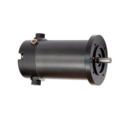
DC motors
Brushed DC motor range
Ningbo EMP DC Motor Dynamics Co., Ltd.- Power
- 0.08–0.2 kW
- M3-012
- 12 V / 80 W / 900 rpm
 0
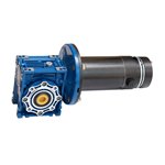
Manufacturer catalogue image · Series illustration

Catalogue series · Exact configuration and availability confirmed by the manufacturer.
The RV assembly turns the drive through a right angle, but its ratio must be checked against the selected gearbox size. EMP’s table shows maximum torque and efficiency changing separately with ratio. The motor winding, output bore, brake and duty remain part of the complete assembly specification.
These values come from the supplier’s parameter table. Its heading says maximum torque; it does not give the service factor, input-speed condition or permissible continuous duty, so these are screening values rather than a continuous-load guarantee.
| Ratio | Listed maximum torque | Dynamic / static efficiency |
|---|---|---|
| 20:1 | 81 Nm | 0.78 / 0.54 |
| 30:1 | 81 Nm | 0.71 / 0.44 |
| 40:1 | 101 Nm | 0.67 / 0.39 |
| 50:1 | 80 Nm | 0.63 / 0.36 |
| 100:1 | 60 Nm | 0.48 / 0.24 |
The size-50 row rises to 101 Nm at 40:1 but falls to 60 Nm at 100:1. Do not multiply the motor torque by ratio alone and assume the gearbox accepts the result. Supply running torque, starting torque, reversals, shock loading and hours of operation for the supplier’s duty selection.
For a calculation example only, 30 Nm at 50 rpm is about 157 W at the output shaft. Using the size-50, 30:1 dynamic efficiency of 0.71 gives about 221 W at the gearbox input and 64 W of gearbox loss. Motor and controller losses are additional. This illustrates the method; actual efficiency and thermal capacity need confirmation at the operating speed and load.
The product page offers an electromagnetic brake as an option. The static-efficiency row is not a certified holding-torque rating or a guarantee that the load cannot back-drive the gearbox. For a load that must remain stationary after power loss, specify the required holding function and have the complete braking arrangement assessed.
Use the drawing designation in the order. A common output bore does not establish the same motor, length or control wiring.
| M3-5656G drawing | The first drawing shows a 14 mm keyed output bore with a 5 mm keyway. Its motor-side axial dimension is 162.2 mm to the gearbox interface, followed by a separate 95 mm gearbox dimension. Check these reference points against the available machine space. |
|---|---|
| M3-6464GB drawing | The second drawing also shows a 14 mm bore and 5 mm keyway, but the corresponding motor-side dimension is 197 mm, 34.8 mm longer. The drawing does not state brake torque or coil voltage, so the GB designation cannot substitute for those electrical and braking details. |
| Do not borrow a Hall pinout from another drawing | Later pages in the same file show M077S and M099S assemblies with Hall-connector details. Those are separately named configurations. Confirm whether the offered motor is brushed or brushless and obtain its own voltage, current and connection sheet; sharing an RV gearbox does not make the motor wiring interchangeable. |
CATALOGUE OVERVIEW
AMOP’s RV right-angle gearmotor combines a brushed DC motor with a worm reduction stage. The product section lists ratios from 5:1 to 100:1, IEC flange and shaft dimensions, and an optional electromagnetic brake. The stated running efficiency is approximately 60%. The much broader 50–50000 W custom-motor offer elsewhere on the page is not an output rating for this RV assembly.
Model / series reference: RV
Specifications describe a series range; confirm which ratings apply together to the quoted model.
Confirm mounting and shaft dimensions against the drawing for the quoted configuration.
DC motors
DC motors
DC motors
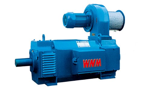
DC motors
Keep your sourcing team on the same page.
We use cookies to keep this site working and measure website usage. Cookie & privacy details
 LinkedIn
 Facebook
 X
 WhatsApp
 Email