

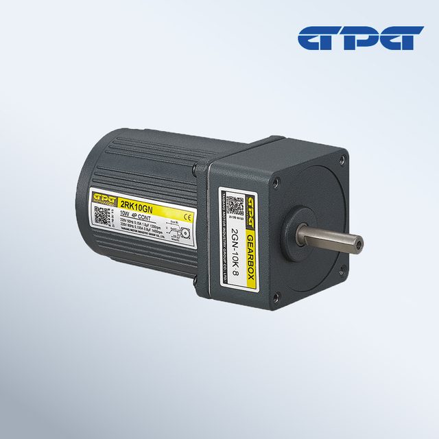
Geared motors
2IK / 2RK 60 mm AC gear motor
TAIBANG MOTOR INDUSTRY GROUP CO., LTD.- Noise
- ≤60 dB (manufacturer-stated)
- Humidity
- Below 95%, non-condensing
 0
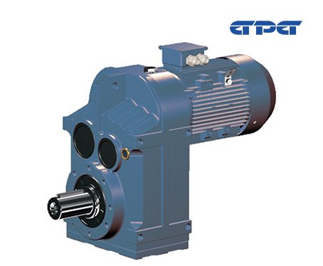
Manufacturer catalogue image · Series illustration

Catalogue series · Exact configuration and availability confirmed by the manufacturer.
A slower FG37 does not provide unlimited torque reserve. In GPG’s 0.75 kW, four-pole selection row, changing the ratio from 24.13 to 41.44 raises listed output torque from 120 to 192 N·m while the catalogue FB value falls from 1.34 to 0.98. Mounting position and shaft connection complete the selection.
These catalogue points use an input speed of 1450 rpm. T2 and FB belong to the selected ratio and motor combination; they are not independent options. Compare your running and starting load with the supplier’s required service-factor criterion before choosing a row.
| Ratio i | Output rpm | T2 N·m | FB |
|---|---|---|---|
| 24.13 | 60.1 | 120 | 1.34 |
| 33.11 | 43.8 | 165 | 1.22 |
| 36.96 | 39.2 | 172 | 1.10 |
| 41.44 | 35.0 | 192 | 0.98 |
The 41.44 ratio reaches the listed 35.0 rpm, but its FB of 0.98 should not be treated as approval for a start-stop conveyor or shock-loaded machine. Give the supplier running torque, breakaway torque, starts per hour and operating hours so the gearbox size and motor combination can be checked together. The six-pole rows in the same FG37 table use 960 rpm input; their output speeds cannot be copied from this four-pole example.
For FG37, the published oil-capacity table lists 1.0 L at M1, 1.2 L at M2, 0.7 L at M3, 1.2 L at M4, 1.0 L at M5 and 1.1 L at M6. Those differences show why rotating an already selected gearbox needs a lubrication review. Identify the orientation on the FGW or FGL installation drawing and obtain the applicable oil-level, vent and service instructions; the capacity table alone is not a filling procedure.
GPG distinguishes a plain hollow shaft (K), a splined hollow shaft (KV, DIN 5480) and a shrink-disc hollow shaft (KH). FGW and FGL drawings also distinguish foot and flange arrangements. Specify the mating shaft dimensions and connection, output side A or B, mounting drawing and terminal-box position. A purchase description containing only “FG37, 0.75 kW” leaves both the reduction ratio and these physical interfaces unresolved.
CATALOGUE OVERVIEW
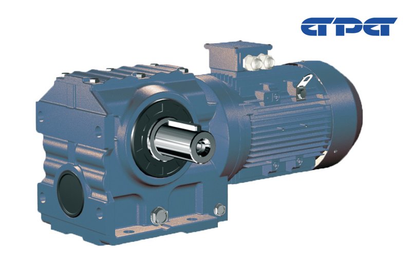
GPG FG parallel-shaft helical gearmotors are offered with foot or flange arrangements and several output-shaft connections. The FG37 selection table pairs each motor power and ratio with output torque and an FB value; mounting positions M1–M6 also have different oil capacities. Use the operating-point comparison below to prepare a ratio, duty and installation specification.
Model / series reference: FG
Specifications describe a series range; confirm which ratings apply together to the quoted model.
Confirm mounting and shaft dimensions against the drawing for the quoted configuration.
Geared motors
Geared motors
Geared motors
Geared motors
Keep your sourcing team on the same page.
We use cookies to keep this site working and measure website usage. Cookie & privacy details
 LinkedIn
 Facebook
 X
 WhatsApp
 Email