

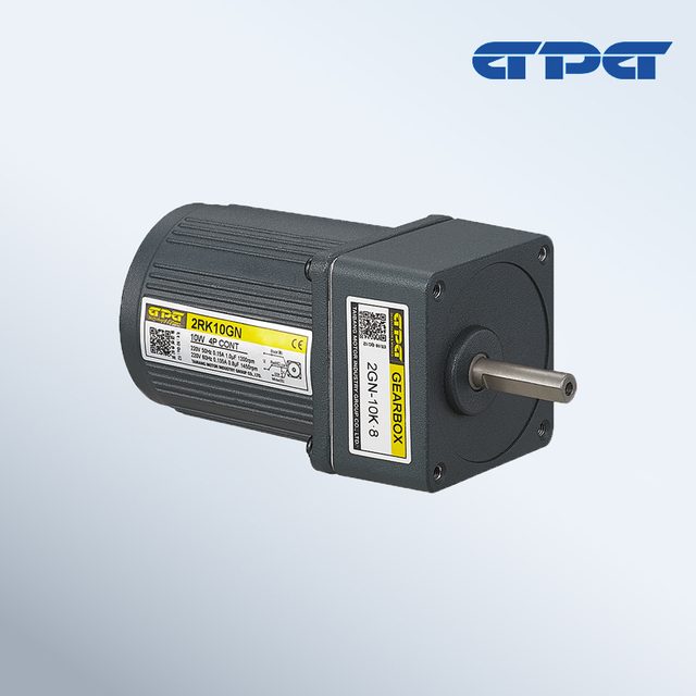
Geared motors
2IK / 2RK 60 mm AC gear motor
TAIBANG MOTOR INDUSTRY GROUP CO., LTD.- Noise
- ≤60 dB (manufacturer-stated)
- Humidity
- Below 95%, non-condensing
 0
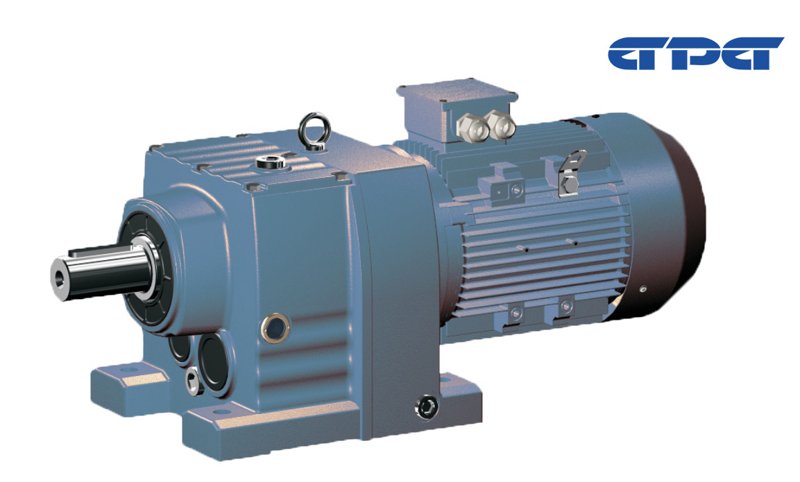
Manufacturer catalogue image · Series illustration

Catalogue series · Exact configuration and availability confirmed by the manufacturer.
GPG’s RG order code treats flange size as a choice within a gearbox size. A 160 mm flange appears on both RGL37 and RGL47, yet the output shafts are 25 and 30 mm respectively. Use the mounting interface and shaft together to avoid an assembly that bolts on but cannot drive the existing coupling.
Dimensions below are in millimetres, transcribed from the RG37 and RG47 outlines. Hole counts and diameters describe the flange pattern. The table compares mechanical interfaces, not torque capacity or complete motor length.
| Flange option | Pilot Ø | Bolt circle Ø | Holes | Shaft Ø | Extension |
|---|---|---|---|---|---|
| RGL37 / Ø120 | 80 h7 | 100 | 4 × Ø7 | 25 k6 | 50 |
| RGL37 / Ø160 | 110 h7 | 130 | 4 × Ø9 | 25 k6 | 50 |
| RGL47 / Ø160 | 110 h7 | 130 | 4 × Ø9 | 30 k6 | 60 |
| RGL47 / Ø200 | 130 h7 | 165 | 4 × Ø11 | 30 k6 | 60 |
RGL37 and RGL47 share the listed 110 h7 pilot and four Ø9 holes on a 130 mm circle in their 160 mm flange versions. Their shafts differ by 5 mm in diameter and 10 mm in extension. Both drawings use an 8 mm key width, which can make a partial measurement misleading. Measure the existing coupling bore and available insertion length, then check the driven equipment’s shaft position against the full assembly drawing.
The RG model explanation uses I for the smaller flange where alternatives exist and II for the larger of two, or the middle of three. Those Roman numerals are not universal flange diameters. Put the gearbox size and actual flange diameter, pilot and hole pattern in the inquiry, and have the supplier return the matching full code. Include the existing ratio and motor nameplate so a matching flange does not accidentally change the machine’s operating speed.
The catalogue separately illustrates an F IEC-flange input, an S shaft input and a combined WB arrangement. On RG37 the S input is shown with a 16 k6 shaft and 40 mm extension; RG47 uses a 19 k6 shaft and the same 40 mm extension. These are input dimensions, not the 25/30 mm output shafts above. State whether you need a complete motor-gearbox assembly or a reducer to accept an existing motor, and supply that motor’s interface drawing when it is being retained.
CATALOGUE OVERVIEW
GPG RG helical gearmotors use foot-mounted RGW or flange-mounted RGL arrangements. The RG37 and RG47 drawings show why a shared 160 mm mounting flange does not make their output shafts interchangeable. Compare the flange, shaft extension and separate motor-side input before choosing a replacement assembly.
Model / series reference: RG
Specifications describe a series range; confirm which ratings apply together to the quoted model.
Confirm mounting and shaft dimensions against the drawing for the quoted configuration.
Geared motors
Geared motors
Geared motors
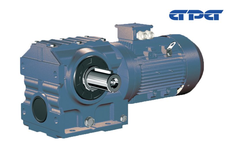
Geared motors
Keep your sourcing team on the same page.
We use cookies to keep this site working and measure website usage. Cookie & privacy details
 LinkedIn
 Facebook
 X
 WhatsApp
 Email