

Application-specific motors
Micro electric drive systems
Zhejiang Founder Motor Co.,Ltd- Power
- 0.06–1.2 kW
- Voltage
- Confirm supply
 0
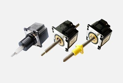
Manufacturer catalogue image · Series illustration

Catalogue series · Exact configuration and availability confirmed by the manufacturer.
SYNTRON’s June 2026 catalogue separates ordinary lead-screw motors from ball-screw motors and offers different mechanical arrangements. The screw type, lead, motor body and load path must be selected together. A small travel increment is not a positioning-accuracy guarantee, and a screw that resists back-driving is not automatically an approved holding brake.
The catalogue describes captive, non-captive and external-drive arrangements. Where the intended output is screw translation, the screw must be prevented from rotating. Establish whether that restraint is built into the selected assembly or supplied by the machine. A motor that spins freely on a bench does not establish usable linear travel in the intended installation.
The manufacturer prohibits radial loading of the screw. Show the carriage guides, offset loads, end supports and couplings on the installation drawing so side forces and overturning moments have a defined path. For a captive assembly, specify usable stroke and end limits: its permitted travel must not be exceeded.
In the ball-screw designation, BS0802 identifies an 8 mm screw diameter and 2 mm lead. Ordinary lead-screw designations encode the lead differently. Body length, phase current, screw length and brake or nut options are additional choices; a 42 mm frame designation alone does not define the assembly that will arrive.
These are the catalogue’s 6.35 mm diameter ordinary lead-screw options, not ball-screw ratings. The last column is the listed unpowered self-locking force, not running thrust or a certified safety holding capacity.
| Lead per revolution | Listed travel per full step | Unpowered self-locking force |
|---|---|---|
| 1.27 mm | 0.00635 mm | 150 N |
| 2.54 mm | 0.0127 mm | 40 N |
| 6.35 mm | 0.03175 mm | 15 N |
| 12.7 mm | 0.0635 mm | 3 N |
| 25.4 mm | 0.127 mm | 0 N |
Linear speed equals lead multiplied by motor revolutions per second. For example, a 2 mm lead at 300 r/min gives 10 mm/s; a 1 mm lead at the same rotation gives 5 mm/s. These are calculated geometric advances, not demonstrated maximum speeds. Establish the acceleration distance, move time and dwell before selecting a curve.
The 42 mm ball-screw charts separate 34, 40, 48 and 60 mm motor bodies and distinguish BS0801, BS0802, BS1202, BS1205 and BS1210. The charts state 40 V, two microsteps, 100% constant current and no acceleration. A starting or accelerating carriage therefore needs separate validation; the largest thrust shown anywhere in the family is not an available thrust at every speed.
The catalogue instructs users to keep actual load below 50% of the motor’s maximum thrust at the actual operating speed. Include friction, gravity where relevant and acceleration force in the load assessment. Selecting against a low-speed graph maximum while running farther along the curve defeats that margin.
The travel-per-step numbers describe command increments. Screw lead error, nut clearance, compliance, load direction and the machine’s referencing method still affect achieved position. Specify allowable absolute error, bidirectional repeatability and backlash separately. An anti-backlash nut is an option for ordinary lead screws; the catalogue notes that it reduces efficiency, so its friction must be included in the drive choice.
The 42 mm tables list body lengths of 34, 40, 48 and 60 mm with phase currents of 1.5, 1.5, 2.5 and 2.5 A respectively. The manufacturer asks for driver RMS current near the motor’s rated current. Record the driver’s current convention; a peak-current dial value must not be treated as the same RMS value.
The illustrated 42 mm motor face has a 31 mm square mounting-hole pattern with four M3 holes. This does not define the ball nut flange, screw supports or carriage clearance. Approve the drawing for the chosen screw and nut, including screw length, usable stroke, home position and the space required at each end.
Provide the orientation and stationary load and state what must happen if power is lost. The ordinary lead-screw table shows that self-locking force falls sharply with increasing lead. Do not transfer those values to a ball screw or rely on them as a brake specification; agree any required brake and independent load restraint for the application.
The catalogue gives an operating ambient range of −20 to 50 °C and says the motor/screw assembly is supplied with special grease that should not be supplemented arbitrarily. Report dust, washdown, contamination and the duty cycle. Ask for the approved lubrication and maintenance instructions for the exact screw type rather than applying a generic grease schedule.
CATALOGUE OVERVIEW
SYNTRON combines a hybrid stepper drive with a screw mechanism to generate linear motion directly. The family includes different screw and shaft arrangements for precision linear positioning, with multiple frame sizes in the manufacturer catalogue.
Select by required thrust, travel, linear speed, screw lead and positioning repeatability rather than rotary holding torque alone. Confirm whether the chosen version uses a ball screw or lead screw, its end support and the permissible side load. Send the installation drawing and motion cycle for model selection.
Model / series reference: Hybrid screw motor
Specifications describe a series range; confirm which ratings apply together to the quoted model.
Confirm mounting and shaft dimensions against the drawing for the quoted configuration.
Application-specific motors
Application-specific motors
Application-specific motors
Application-specific motors
Keep your sourcing team on the same page.
We use cookies to keep this site working and measure website usage. Cookie & privacy details
 LinkedIn
 Facebook
 X
 WhatsApp
 Email