

Servo motors
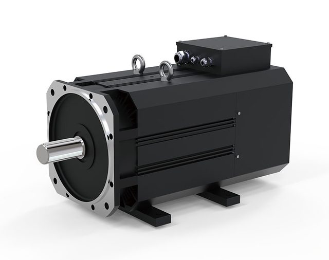
AGV servo motor
Zhejiang Lianyi Electric Co.,Ltd.- Control
- Current, speed and position feedback
- Application
- Automated guided vehicles
 0
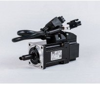
Manufacturer catalogue image · Series illustration

Catalogue series · Exact configuration and availability confirmed by the manufacturer.
MiGe’s 40A data demonstrates why the short servo name is not enough. The 50 W and 100 W groups each have 48 V and 220 V windings, with different current and peak-torque ratings. The same source also shows different motor-power connector assignments for incremental and absolute encoder configurations. A replacement needs the complete motor and feedback specification, not just wattage and flange size.
The 50 W short designation is 40AST-M00130; the 100 W designation is 40AST-M00330. Standard codes are MN040-P16FBD12-01A000 and MN040-P16FED12-01A000 for the 50 W pair, and MN040-P32FBD12-01A000 and MN040-P32FED12-01A000 for the 100 W pair. FBD corresponds to the 48 V row and FED to the 220 V row in this sheet.
| Winding | Rated current | Rated / peak torque | Line-to-line R / L | Rotor inertia | Mass |
|---|---|---|---|---|---|
| 50 W / 48 V | 1.1 A | 0.16 / 0.48 N·m | 6.75 Ω / 7.5 mH | 0.025 × 10⁻⁴ kg·m² | 0.32 kg |
| 50 W / 220 V | 0.4 A | 0.16 / 0.32 N·m | 108 Ω / 108 mH | 0.025 × 10⁻⁴ kg·m² | 0.32 kg |
| 100 W / 48 V | 2.5 A | 0.32 / 0.95 N·m | 2.2 Ω / 3 mH | 0.051 × 10⁻⁴ kg·m² | 0.47 kg |
| 100 W / 220 V | 0.6 A | 0.32 / 0.64 N·m | 34 Ω / 40 mH | 0.051 × 10⁻⁴ kg·m² | 0.47 kg |
Both 50 W windings have 0.16 N·m rated torque, yet their listed peaks are 0.48 and 0.32 N·m. The 100 W pair likewise differs at 0.95 versus 0.64 N·m. Do not transfer the low-voltage peak to the 220 V winding. The public table does not specify how long those peaks are permitted; provide acceleration, load inertia and repetition rate to obtain an approved duty from the motor/drive supplier.
The 48 V and 220 V values identify different motor winding rows. They do not establish direct connection to a DC supply or mains without the matching servo drive. Current, resistance and inductance change markedly between the windings. Specify the drive model, its motor parameter set and current-rating convention rather than selecting a drive solely from the same wattage label.
The incremental configuration’s four-pin table assigns pins 1–4 to U, V, W and PE. The absolute configuration assigns pins 1–4 to PE, U, V and W. This is a material wiring difference even before considering the encoder cable. Obtain the exact pinout and mating-connector orientation for the delivered version; do not reuse a cable because the connector shell fits.
The source lists 2,500 encoder lines and separately shows a 15-pin incremental connector and a seven-pin absolute connector. The latter has E−, E+, SD−, 0 V, SD+, +5 V and PE labels. These labels alone do not define a compatible absolute protocol or resolution. Ask for the encoder variant, drive compatibility, cable shielding and pin diagram as part of the order.
The length table gives L = 75 mm for the 50 W group without a brake and 90 mm for the 100 W group. With either listed permanent-magnet or electromagnetic brake option, L becomes 109 or 124 mm respectively. The table does not give brake holding torque or stopping energy. State whether the job needs stationary holding or dynamic stopping and obtain the corresponding brake specification; body-length availability is not brake-performance approval.
The drawing shows a 40 mm square face, a 30 mm register, an 8 mm shaft extending 25 mm and four 3.5 mm mounting holes on a 46 mm bolt circle. The upper connector region extends to a shown 53.5 mm envelope dimension. Verify the complete toleranced drawing, cable clearance and L for the chosen brake configuration before mounting.
The 40A sheet lists class B insulation, IP65, −20 to 40 °C ambient and humidity below 90% without condensation. Confirm protection with the actual connectors and installation. These are 40A sheet entries, not automatic ratings for MiGe’s larger A, B, E or N motor families, and they do not replace the application’s thermal-duty check.
CATALOGUE OVERVIEW
MiGe’s servo catalogue separates A, B, E and N motor families. The reviewed 40A sheet provides a concrete comparison within that range: 50 W versions deliver 0.16 N·m rated torque at 3000 rpm, and 100 W versions deliver 0.32 N·m at the same speed. Both 48 V and 220 V windings are shown. Peak torque differs between windings even at the same rated power.
For example, the 50 W sheet lists 0.48 N·m peak at 48 V versus 0.32 N·m at 220 V. Matching only the 40AST designation or wattage is therefore insufficient. Supply the full winding code, drive voltage, feedback interface, brake requirement and peak-duty cycle; these 40A values must not be applied to larger B-series motors.
Specifications describe a series range; confirm which ratings apply together to the quoted model.
Confirm mounting and shaft dimensions against the drawing for the quoted configuration.
Servo motors
Servo motors
Servo motors
Keep your sourcing team on the same page.
We use cookies to keep this site working and measure website usage. Cookie & privacy details
 LinkedIn
 Facebook
 X
 WhatsApp
 Email