

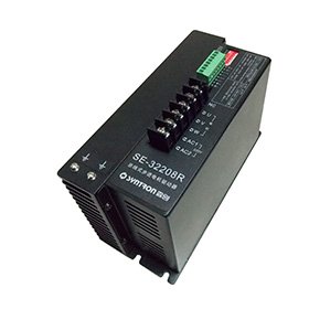
Motor parts & accessories
SE bus-controlled stepper driver series
Beijing Senchuang Motion Control (SYN-TRON)- Bus Options
- RS485 / CANopen / EtherCAT; model dependent
- Product Type
- Stepper driver
 0
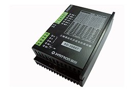
Manufacturer catalogue image · Series illustration

Catalogue series · Exact configuration and availability confirmed by the manufacturer.
SD is a family name, not a single interchangeable driver. The SD-20504EK and SD-32210SK manuals show two materially different choices: a low-voltage two-phase pulse/direction unit and a higher-voltage three-phase unit with additional operating modes and outputs. The distinctions below come from their July 2026 manuals and apply to those full references.
Its diagram uses A+, A−, B+ and B− motor terminals and a 24–50 V DC supply. The 4.2 A maximum is peak current per phase, not a DC power-supply current rating. Check the motor winding connection and current convention before choosing one of the eight 1.0–4.2 A settings. The EK manual provides standard pulse-plus-direction control.
Its motor terminals are U, V and W. The performance table specifies 90–350 V DC or 70–245 V AC input and 10.2 A peak per phase maximum. This is not a higher-current replacement for the two-phase EK unit. The typical AC wiring drawing separately labels 80–220 V AC, so confirm the approved input range for the offered hardware before designing the supply around either endpoint.
Both manuals specify a 200 kHz pulse-response ceiling, at least 2 µs effective pulse time and at least 2 µs direction setup. The physical interface and enabled operating mode still need to match the controller.
| Control requirement | SD-20504EK | SD-32210SK |
|---|---|---|
| External command modes documented | Pulse + direction | Pulse + direction; dual pulse |
| Other speed-control modes documented | Not specified in this manual | Internal pulse generation; potentiometer |
| Selectable steps per revolution | 16 settings, 200 to 25,600 | 16 settings, 400 to 51,200 |
| Control input voltage range | 5–24 V | 5–24 V |
| Alarm / brake-control outputs | Not shown in the EK interface | Optically isolated outputs; 50 mA maximum in output diagram |
| Enclosure dimensions | 118 × 75.5 × 34 mm | 150 × 97.5 × 52.5 mm |
Standstill-current reduction and the FREE input have different effects. These details matter for a machine that must hold position between moves.
For SD-20504EK with SW4 OFF, the manual says that after 0.4 seconds without a new pulse, phase current falls to 60% of the set value. For SD-32210SK the stated automatic reduction after 0.4 seconds is to one half. Do not carry the EK switch meaning over to the SK model or assume identical standstill holding performance. Confirm the load can be held with the selected idle-current behaviour.
Both manuals describe the active FREE input as cutting motor phase current and leaving the rotor free. If the machine relies on motor torque to retain a load, design its hold and release sequence accordingly. The SK brake-control output is a signal output for an appropriate relay circuit; the 50 mA interface rating is not permission to power an arbitrary brake coil directly.
The manuals state approximately one second for power-on reset before commands can be answered. Current and microstep changes take effect immediately, so the manuals prohibit arbitrary DIP-switch changes during normal operation. Record the approved switch configuration and controller steps-per-unit together before commissioning.
Both units list −5 to +40 °C operating ambient and relative humidity below 80%, without condensation or frost. Their installation notes call for at least 5 cm between adjacent drivers and separation of power wiring from control signals. Use the actual cabinet temperature, supply and motor current to review cooling; the small enclosure dimensions alone do not determine the required cabinet footprint.
CATALOGUE OVERVIEW
The SYNTRON SD family provides digital control for compatible stepper motors using a DSP-based architecture and microstepping. The model table separates supply voltage, phase count, maximum current and supported motor sizes.
For example, the July 2026 SD-20504EK manual specifies 24–50 V DC and up to 4.2 A peak per phase. The SD family also includes three-phase motor drivers with different supply and control requirements; the full suffix matters. Select the exact driver by motor winding current and required pulse interface; the supply rating is not a motor output-power rating. Ask for wiring diagrams and alarm behaviour for your machine controller.
Model / series reference: SD
Specifications describe a series range; confirm which ratings apply together to the quoted model.
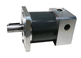
Confirm mounting and shaft dimensions against the drawing for the quoted configuration.
Motor parts & accessories
Motor parts & accessories
Motor parts & accessories
Motor parts & accessories
Keep your sourcing team on the same page.
We use cookies to keep this site working and measure website usage. Cookie & privacy details
 LinkedIn
 Facebook
 X
 WhatsApp
 Email