

Motor parts & accessories
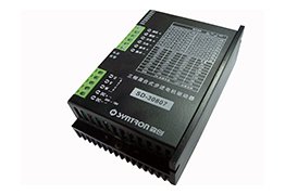
SD digital stepper driver series
Beijing Senchuang Motion Control (SYN-TRON)- Product Type
- Stepper driver
- Example Model
- SD-20504EK
 0
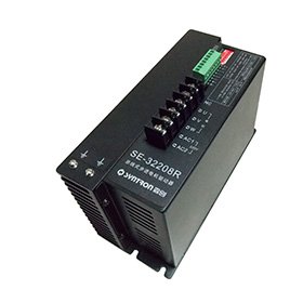
Manufacturer catalogue image · Series illustration

Catalogue series · Exact configuration and availability confirmed by the manufacturer.
A network connection does not make all SE drivers compatible with the same PLC program. The documented SE-20403R uses RS-485 with Modbus RTU; SE-20806C uses CANopen. Their electrical ratings, address selection and physical inputs differ. EtherCAT is listed elsewhere in the family, but it is not a feature of either example below.
SE-20403R values are from the October 2022 manual; SE-20806C values are from the July 2025 manual. Both are still linked from the manufacturer’s SE page. Current hardware and firmware should be identified in the offer.
| Requirement | SE-20403R | SE-20806C |
|---|---|---|
| Bus / protocol | RS-485 / Modbus RTU | CAN / CANopen |
| DC supply | 12–40 V | 24–70 V |
| Maximum phase current | 3 A peak | 6 A peak |
| Programmable isolated inputs | 2 | 3 |
| Switch-selected addresses | 1–8 | 1–4 |
| Communications-selected address range | 1–247 | 1–127 |
| Enclosure dimensions | 92 × 55 × 21 mm | 135 × 77 × 46 mm |
Select one protocol and obtain its matching register or object documentation. A long address range does not establish how many axes can meet the required cycle time on a real network.
The SE-20806C manual specifies 250 kbit/s when SW6 selects the hardware configuration. Its communications configuration supports 20, 50, 100, 125, 250, 500 and 1000 kbit/s and states that baud-rate changes require power cycling. Request the matching object dictionary and device description for the firmware, then agree the node address, controller mode, communication-loss response and restart behaviour. Do not assume that selecting CANopen in a PLC automatically supplies a compatible motion setup.
For SE-20403R, the register table says current and microstep changes become effective after power cycling; several motion parameters become effective when the start command is inactive. Its hardware-selected setting is 9600 bit/s. The manual’s switch description and baud-register note conflict about the SW4 state for communications-selected baud rate, so confirm this on the delivered revision rather than embedding an assumed setting in a production program.
The R manual describes speed, periodic position and point-to-point position control; the C manual describes its own CANopen modes. Specify absolute versus relative commands, the scaling between command units and machine travel, acceleration/deceleration and the required update period. Reading driver status over a bus is not evidence of encoder-confirmed shaft position: the manufacturer places these units in its open-loop driver range.
Both manuals describe a debug mode entered with SW5 ON before power-up, in which changing SW5 can command 200 r/min test rotation. Record the normal operating switch state, firmware and saved parameters in the commissioning handover. A replacement should be checked in a controlled setup before connection to a load that could move unexpectedly.
Its manual shows input 1 with an internal 330 Ω resistor and calls for added current limiting at higher signal voltages: 1 kΩ at 12 V and 2 kΩ at 24 V. Inputs 2 and 3 are separately specified for 3–24 V signals. Give the PLC output type and voltage to the supplier and obtain the wiring approval for each terminal; do not wire all three inputs as if their circuits were identical.
Both selected manuals state that after 0.1 seconds at zero speed, phase current reduces to 50% of the set value. Check the machine’s stationary load requirement under that behaviour and agree how power loss and network loss are handled. Neither bus communications nor a software stop should be treated as a mechanical holding brake.
SE-20806C lists 24–70 V DC operation, with undervoltage and overvoltage protection thresholds below 20 V and above 90 V respectively. Those alarm thresholds do not extend its normal supply range. Provide the supply tolerance and deceleration duty so regenerative voltage rise can be assessed along with the motor and cabinet cooling.
CATALOGUE OVERVIEW
SYNTRON SE drivers support network-controlled stepper systems. The range includes RS485, CANopen and EtherCAT variants, with model-dependent voltage and output current. Published control modes include point-to-point positioning, speed control and periodic position control.
Select the communication protocol and motor phase count before matching current and supply. Confirm the device profile, supported cycle time and control software against your PLC or motion controller. This listing covers a drive component and does not include a motor.
Model / series reference: SE
Specifications describe a series range; confirm which ratings apply together to the quoted model.
Confirm mounting and shaft dimensions against the drawing for the quoted configuration.
Motor parts & accessories
Motor parts & accessories
Motor parts & accessories
Motor parts & accessories
Keep your sourcing team on the same page.
We use cookies to keep this site working and measure website usage. Cookie & privacy details
 LinkedIn
 Facebook
 X
 WhatsApp
 Email