

Stepper motors
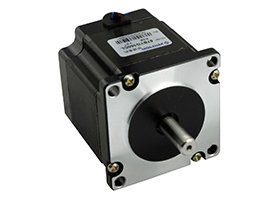
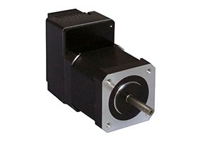
Three-phase hybrid stepper motor series
Beijing Senchuang Motion Control (SYN-TRON)- Phases
- Three
- Step Angle
- 1.2°
 0
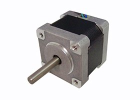
Manufacturer catalogue image · Series illustration

Catalogue series · Exact configuration and availability confirmed by the manufacturer.
A two-phase frame size is not a complete replacement specification. In SYNTRON’s July 2026 42(K) manual, each A, B and C body is offered with a single shaft or a shaft at both ends. The paired versions share the listed electrical ratings, but the rear shaft changes the space and mechanical interface the machine must accommodate.
The listed 42BYG250AK, BK and CK single-shaft versions end in SASSML-0151. Their front shaft is 5 mm in diameter and extends 24 mm; the drawing gives a 42.3 mm square face, 22 mm register and four M3 holes on a 31 ±0.1 mm square pattern. Match the register and shaft tolerances on the approved drawing, not just the nominal frame label.
The corresponding BASSML-0151 versions add a 5 mm rear shaft extending 10 mm. The body lengths remain 34, 40 and 48 mm for A, B and C. This is a mechanical extension, not evidence that an encoder is included or that the motor operates closed loop. Check the rear attachment and guarding envelope before substituting a double-shaft motor.
The naming key allows shaft shape, length and connection variations and identifies Ver*.* as a custom version. The selected table uses four-lead motors; the broader key also describes an eight-lead option. Do not apply the four-lead wiring diagram to a differently terminated custom motor merely because its frame and current appear similar.
The data apply to 42BYG250AK/BK/CK with the SASSML-0151 or BASSML-0151 suffixes listed in the manual. The no-load starting-frequency column is measured at 24 V DC in half-step operation; it is not a loaded start-speed specification.
| Body | Holding torque | Inductance / resistance | Inertia / mass | Length L | No-load start |
|---|---|---|---|---|---|
| A | 0.23 N·m | 2.1 mH / 1.3 Ω | 38 g·cm² / 0.21 kg | 34 mm | 1.6 kHz |
| B | 0.43 N·m | 5.0 mH / 2.1 Ω | 57 g·cm² / 0.23 kg | 40 mm | 1.5 kHz |
| C | 0.54 N·m | 3.85 mH / 2.0 Ω | 82 g·cm² / 0.36 kg | 48 mm | 1.5 kHz |
At a 0.9° half-step setting there are 400 commanded steps per revolution. Thus 1.5 kHz corresponds geometrically to 225 r/min, but the catalogue’s start figure is specifically no-load. A machine carrying inertia or friction may need an acceleration ramp instead of an instantaneous start at that command rate. State the actual load and required move time.
The A, B and C torque plots use 24 V DC and 0.9° steps and show torque declining with frequency. Their stationary holding values do not define running torque across the speed range. The B motor also has more inductance than C despite less holding torque. Select from the relevant curve and confirm the driver settings rather than extrapolating performance from body length or current alone.
For the standard four-lead version, the manual shows red A+, blue A−, green B+ and black B−. It explicitly warns against incorrect phase connections. Record those winding pairs and the actual driver terminal assignments during replacement. The listed typical drivers are SD-20403 and SD-20504; obtain the exact revision and current-setting convention with the offer.
The manufacturer requires front-register location and motor/load shaft concentricity, warning that misalignment can bend or break the shaft. It specifies 0 to 50 °C operating ambient, humidity below 85% RH and class B insulation. Include coupling, mounting heat path, move/dwell cycle and ambient in the acceptance setup; successful unloaded bench rotation is not the whole test.
CATALOGUE OVERVIEW
SYNTRON offers two-phase hybrid stepper motors for incremental positioning. The catalogue includes 28, 35, 39, 42, 56, 86 and 110 frame families with model-specific current, resistance and holding-torque tables. The listed step angle is 1.8 degrees.
As a selection example, the 42BYG250BK-0151 is listed at 1.5 A and 0.43 N·m holding torque. Holding torque describes the energized stationary condition, not available torque at running speed. Select the driver supply, acceleration and load from the torque-speed curve for the exact winding.
Model / series reference: Two-phase hybrid
Specifications describe a series range; confirm which ratings apply together to the quoted model.
Confirm mounting and shaft dimensions against the drawing for the quoted configuration.
Stepper motors
Stepper motors
Stepper motors
Stepper motors
Keep your sourcing team on the same page.
We use cookies to keep this site working and measure website usage. Cookie & privacy details
 LinkedIn
 Facebook
 X
 WhatsApp
 Email