

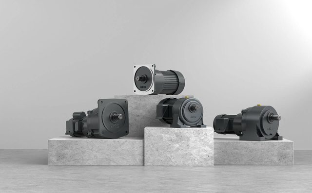
Geared motors
Small gear motor range
SANMEN TAILI MOTOR CO., LTD.- Power
- 0.1–7.5 kW
- Supply Options
- Single phase / three phase
 0
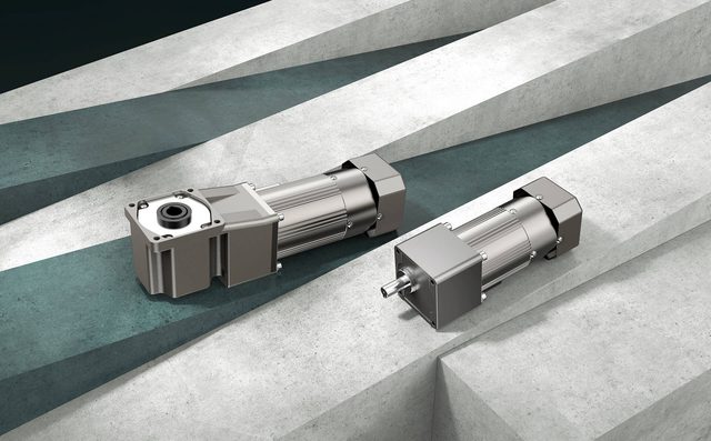
Manufacturer catalogue image · Series illustration

Catalogue series · Exact configuration and availability confirmed by the manufacturer.
TAILI’s miniature AC catalogue covers several frame sizes and both parallel-shaft and right-angle arrangements. The 80 mm, 25 W parallel-shaft example below shows why wattage alone is insufficient: the induction, reversible and brake versions have different duty entries, and higher reduction eventually stops increasing the permissible output torque. These figures belong to that example, not every motor in the wider range.
The original motor table combines 25/40 W entries. These are the operating-type and supply distinctions shown there; the capacitor must match the exact voltage and motor order. The brake entries describe motor duty, not permitted brake cycling or brake holding torque.
| Operating type | Supply shown | Rated time | Ordering consequence |
|---|---|---|---|
| Induction, IK | 1-phase 110/220 V; 3-phase 220/380 V | Continuous | Choose the winding and round or gear-shaft version. |
| Reversible, RK | 1-phase 110/220 V | 30 minutes | Do not substitute into a continuous-duty job solely on wattage. |
| Brake, IK with M suffix | 1-phase 110/220 V | 30 minutes | Include run/rest duty and the required brake function. |
| Brake, IK with M suffix | 3-phase 220/380 V | Continuous | Confirm brake supply and stopping duty separately. |
| Speed-regulating, R variant | 1-phase 110/220 V | Continuous | Specify controller and required torque at low speed. |
These selected points are from the 0.025 kW permissible-torque rows. Speeds are catalogue calculations using 1,400 rpm at 50 Hz or 1,680 rpm at 60 Hz divided by the ratio; actual speed changes with load. The 8 N·m plateau is a listed gearbox limit, not an instruction to multiply motor torque indefinitely.
| Ratio | 50 Hz output rpm | 50 Hz permissible torque | 60 Hz output rpm | 60 Hz permissible torque |
|---|---|---|---|---|
| 10:1 | 140 | 1.59 N·m | 168 | 1.28 N·m |
| 30:1 | 47 | 4.67 N·m | 56 | 3.75 N·m |
| 50:1 | 28 | 7.16 N·m | 33.6 | 5.76 N·m |
| 60:1 | 23.3 | 8 N·m | 28 | 6.91 N·m |
| 100:1 | 14 | 8 N·m | 16.8 | 8 N·m |
| 300:1 | 4.7 | 8 N·m | 5.6 | 8 N·m |
For the 25 W speed-regulating entry, the table lists 0.07 N·m motor torque at 90 rpm and 0.19 N·m at 1,400 rpm for 50 Hz operation. Reducing motor speed with the controller therefore does not preserve full-speed rated torque. Calculate the load at the chosen motor speed and reduction ratio; the fixed-speed gearbox table above cannot by itself validate a 90 rpm motor operating point.
TAILI distinguishes gear-shaft matching for 2–250K, 300K and 400–600K, and warns against heavy loads above 300K. It also offers a 10:1 intermediate reducer for additional reduction. Include that reducer explicitly in the order and obtain the complete assembly’s permissible torque and dimensions. Adding another reduction stage is not proof of ten times the allowed output torque.
The 25 W GK fixed-speed assembly is dimensioned 159.5 mm in body length, while its speed-regulating version is 170.5 mm. The corresponding brake assemblies are 200 and 211 mm. The illustrated gearbox output shaft is 10 mm diameter with 30.5 mm projection; the separate round-shaft motor drawing shows an 8 mm shaft. Use the gearbox-output drawing for the driven coupling, rather than the bare motor’s shaft size.
The illustrated 80 mm front uses a 66.5 mm square mounting pattern. A terminal-box version adds space above the motor, and a speed-regulating version includes a rear section. Send the available length, overhead clearance and desired shaft orientation with the enquiry. Those 80 mm drawings do not establish the dimensions of the 60, 70, 90, 104 or 120 mm catalogue alternatives, or the right-angle range.
For the listed single-phase examples, the capacitor entries are 6 µF/250 VAC at 110 V and 2 µF/450 VAC at 220 V. Have the exact motor and capacitor combination confirmed, particularly when replacing an existing assembly. Include line frequency, direction changes, continuous or timed running, required output rpm, running and starting load, and whether a brake or speed controller is part of the supply.
CATALOGUE OVERVIEW
Taili’s miniature geared-motor catalogue covers listed variants from 6 W to 1.5 kW. Motor face sizes include 60, 70, 80, 90, 104 and 120 mm across the range. Parallel-shaft and right-angle configurations appear in the catalogue. Select the motor, gear ratio and output-shaft arrangement together, and confirm output torque and permissible radial load using the matched assembly drawing.
Specifications describe a series range; confirm which ratings apply together to the quoted model.
Confirm mounting and shaft dimensions against the drawing for the quoted configuration.
Geared motors
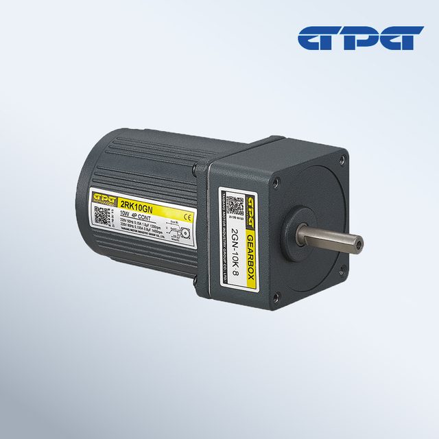
Geared motors
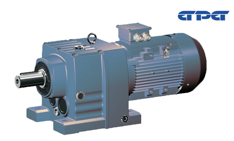
Geared motors
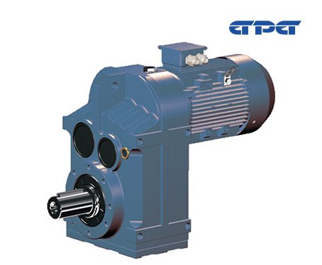
Geared motors
Keep your sourcing team on the same page.
We use cookies to keep this site working and measure website usage. Cookie & privacy details
 LinkedIn
 Facebook
 X
 WhatsApp
 Email