
Motor parts & accessories
Commercial vehicle electronic control systems
Zhejiang Founder Motor Co.,Ltd- Application
- Commercial vehicles
- Product Type
- Vehicle electronic control system
 0
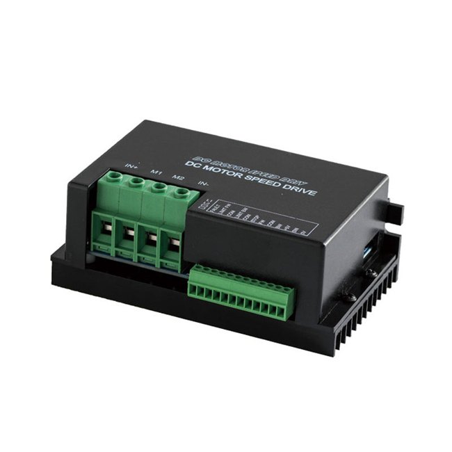
Manufacturer catalogue image · Series illustration

Catalogue series · Exact configuration and availability confirmed by the manufacturer.
EMP’s controller catalogue includes substantially different drive types. DC24RT100BL is explicitly listed for permanent-magnet brushed motors despite its BL suffix. DBLS-07-H is a brushless drive with much higher input voltage. Neither the common catalogue page nor a similar name establishes that two controllers can operate the same motor.
The product page lists 12–48 V DC and permanent-magnet brushed motor control. The linked RT manual describes four-quadrant regenerative PWM operation, speed and direction control, and separate enable, brake and reverse inputs. This is the branch to investigate for a brushed PMDC motor; the letters BL in its part name are not a brushless-motor compatibility statement.
The separate product page specifies 85–265 V AC at 50/60 Hz or 120–375 V DC, 12 A continuous output and brushless motors below 1,500 W. It does not establish the motor’s required winding voltage or feedback wiring. Supply the full motor designation and request the matching terminal and commutation documentation before selecting this drive; it is not a substitute on a 24 V battery system.
The linked RT manual lists voltage variants under combined DC12/24/36/48 designations. Its table gives 10–55 V input and 12–48 V output across the group. Use the exact voltage variant and approved operating range in the order, rather than assuming every unit automatically accepts every battery voltage.
| RT group in manual | Continuous current in manual | Peak current in manual | Listed dimensions / mass |
|---|---|---|---|
| RT30BL | 15 A | 30 A | 127 × 97 × 48 mm / 0.9 kg |
| RT50BL | 30 A | 50 A | 135 × 135 × 70 mm / 0.9 kg |
| RT100BL | 70 A — conflicts with product page | 100 A | 212 × 115 × 63 mm / 1.5 kg |
The DC24RT100BL product page states 50 A continuous and 100 A peak for 20 seconds, while its linked RT family manual lists 70 A continuous for RT100BL. These are different published claims. Ask for the delivered hardware revision, continuous rating and cooling conditions in writing; do not size a continuous load on the higher value or treat the 100 A peak as continuous capability.
Provide starting, running and reversal current together with how long each lasts, the repetition interval and ambient conditions. The RT manual says thermal protection first reduces output current and then stops output if temperature remains high. A short successful run therefore does not demonstrate continuous operation without derating.
The RT manual describes regenerative braking and adjustable braking current. Specify whether the source is a battery or a DC supply and whether it can accept returned energy. Request the approved arrangement for the actual source, overvoltage response and stopping duty. Regenerative braking is not a claim of holding a load after power loss.
The manual lists 0–5 V analogue or potentiometer control, a 10 kΩ / 2 W potentiometer, input impedance of at least 50 kΩ and adjustable soft start from 0.2 to 20 seconds. It separately describes enable, brake and reverse terminals operated through dry contacts or transistor open-collector control. Obtain the terminal drawing and normal/fault states for the exact unit; these functions are not interchangeable names for one stop command.
The RT document describes current and voltage PI loops and a 1:80 speed-control ratio. It does not establish encoder feedback for the offered motor or guaranteed speed regulation at every load. State the required low-speed smoothness and load-change response and agree a test using the actual motor, especially when the application spends long periods near its lowest speed.
CATALOGUE OVERVIEW
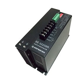
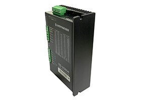
EMP’s controller catalogue lists DC24RT100BL, DC24RT30BL, KLS2412N, KLS-8080N/NPS, KLS7275H, KLS-4818N, DBLS-07-H, HPBL1000, HPBL3000 and KLS-4830ND. These are drive controllers, not bare motors. Choose the exact controller using battery or bus voltage, motor commutation and current limits; the catalogue’s shared motor-power filter does not establish each controller’s rating.
Specifications describe a series range; confirm which ratings apply together to the quoted model.
Confirm mounting and shaft dimensions against the drawing for the quoted configuration.
Motor parts & accessories
Motor parts & accessories
Motor parts & accessories
Motor parts & accessories
Keep your sourcing team on the same page.
We use cookies to keep this site working and measure website usage. Cookie & privacy details
 LinkedIn
 Facebook
 X
 WhatsApp
 Email