

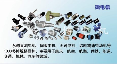
DC motors
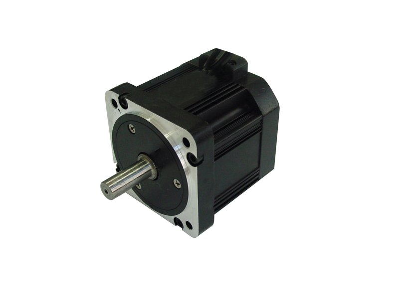
Industrial DC motor range
SHANDONG SHANBO MOTOR GROUP CO.,LTD- Applications
- Vehicle drives / servo / switchgear
- Catalogue Families
- SZ / ZY / ZYT / SY / ZCF; geared DC
 0
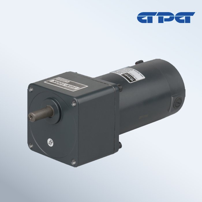
Manufacturer catalogue image · Series illustration

Catalogue series · Exact configuration and availability confirmed by the manufacturer.
GPG’s miniature DC catalogue contains separate 12 V and 24 V windings, several motor speeds and optional brake modes. Its current and millinewton-metre figures describe the motor-side selection; they must not be mistaken for controller peak ratings or the geared output shaft’s torque.
These pairs come from the listed 1500 rpm rows. Each voltage is a separate catalogue winding choice, not permission to switch one motor between 12 and 24 V. Motor-family labels below follow the grouped table entries; confirm the full winding and shaft suffix in the order.
| Motor group / output | 12 V current | 24 V current | Motor torque |
|---|---|---|---|
| GDM69 / 25 W | 3.8 A | 1.75 A | 159.08 mN·m |
| GDM69-08 / 40 W | 6.1 A | 2.78 A | 254.6 mN·m |
| GDM80 / 60 W | 9.1 A | 4.2 A | 382 mN·m |
The 40 W, 24 V entry lists 2.78 A, but that is not a published stall or acceleration-current limit. Supply the controller vendor with the selected winding, load inertia, starting load and reversal frequency. Request the motor’s peak-current information and agree current limiting and protection; do not size a battery fuse or drive solely by the tabulated running-current value.
For the GDM69 40 W group, the table lists 254.6 mN·m at 1500 rpm, 212 mN·m at 1800 rpm and 173.6 mN·m at 2200 rpm. The first figure is 0.2546 N·m, not 254.6 N·m. A separate 3200 rpm row is labelled for a plain shaft. None of these is a universal low-speed output rating; state the gear ratio, required output speed and continuous/peak load so the chosen gearhead can be checked.
The accessory key identifies M as electromagnetic braking on power-off and M2 as electromagnetic braking on power-on. Specify the intended stopping and holding sequence rather than ordering “with brake” alone. Ask for the selected brake’s coil supply, torque and duty; the accessory code does not provide those ratings or establish a safety-rated holding function.
For the drawn GDM69/105-07SC assembly, ratios 1:3–1:20 use L2 = 32 mm and L3 = 137 mm. Ratios 1:25–1:300 use L2 = 42 mm and L3 = 147 mm. The motor-side L1 stays 105 mm. Leave room for that 10 mm change when the gearbox is located inside a housing; L3 is the labelled drawing span, not a substitute for every external clearance.
The same 70 mm gearhead drawing shows a 10 h7 output shaft and 25 mm extension. The motor drawings separately distinguish SA plain-shaft and SC geared-shaft arrangements. Send the existing front mounting pattern, output coupling dimensions and full motor/gearhead codes with the inquiry, so a matching 70 mm face is not mistaken for an interchangeable motor pinion or winding.
CATALOGUE OVERVIEW
GPG miniature DC gearmotors use selectable DC windings, motor speeds and gearheads. The attached catalogue includes paired voltage/current data, motor torque in mN·m, SA/SC shaft arrangements and M/M2 brake options. Use the examples below to separate electrical selection from geared output performance and mounting space.
Model / series reference: Miniature DC geared
Specifications describe a series range; confirm which ratings apply together to the quoted model.
Confirm mounting and shaft dimensions against the drawing for the quoted configuration.
DC motors
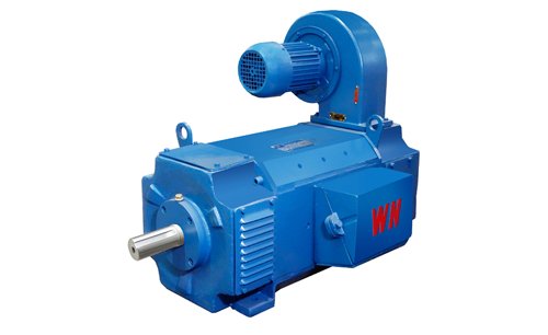
DC motors
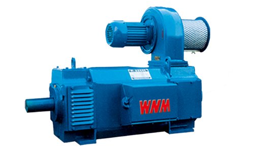
DC motors
DC motors
Keep your sourcing team on the same page.
We use cookies to keep this site working and measure website usage. Cookie & privacy details
 LinkedIn
 Facebook
 X
 WhatsApp
 Email