

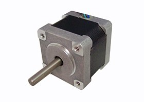
Stepper motors
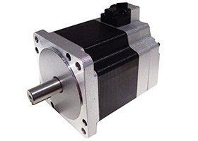
Two-phase hybrid stepper motor series
Beijing Senchuang Motion Control (SYN-TRON)- Step Angle
- 1.8°
- Example Model
- 42BYG250BK-0151
 0
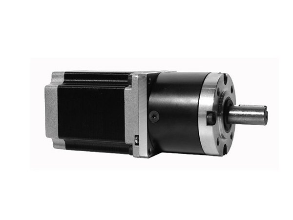
Manufacturer catalogue image · Series illustration

Catalogue series · Exact configuration and availability confirmed by the manufacturer.
This assembly is a 57 mm hybrid stepper coupled to an M56GXR planetary reducer. Increasing the ratio changes gearbox length, efficiency and permitted output torque. It does not simply multiply the motor’s stationary holding torque into a usable running rating. The official combined drawing supplies separate gearbox and motor tables, which need to be used together.
Nominal ratios are ordering labels. The source separately lists exact ratios for motion calculations. Length L1 is the reducer body dimension in the drawing, not the total motor-and-gearbox length.
| Stages | Nominal ratios | Permitted output torque | Listed efficiency | Reducer L1 | Approx. reducer mass |
|---|---|---|---|---|---|
| 1 | 3.6, 4.3 | 2 N·m | 80% | 40.0 mm | 500 g |
| 2 | 13, 15, 18 | 8 N·m | 70% | 51.3 mm | 600 g |
| 3 | 47, 55, 65, 77 | 16 N·m | 60% | 62.6 mm | 700 g |
| 4 | 168, 198, 234, 276, 326 | 20 N·m | 50% | 73.9 mm | 850 g |
For that two-stage option, 100 r/min at the output requires 1,296 r/min at the input, calculated using the published exact ratio. Nominal 4.3 is 4.25; nominal 168 is 167.96. Use the approved exact ratio in the machine’s pulse-to-travel scaling, especially when repeated travel must return to a reference position.
The drawing gives output torque as motor torque × ratio × efficiency. As an illustrative calculation only, an available running motor torque of 0.5 N·m with ratio 12.96 and the listed 70% efficiency gives about 4.54 N·m. That lies below the two-stage reducer’s 8 N·m limit, but the 0.5 N·m must first be established at the actual input speed and drive conditions; it is not a published motor rating here.
The gearbox table lists 3,000 r/min rated input speed and 7,000 r/min maximum input speed. Those entries do not establish that a selected 57HS winding can start or deliver the required torque at those speeds. Submit the move time, acceleration, reflected load inertia and motor driver voltage for a torque–speed check.
The source labels the backlash row in arcminutes but puts degree symbols against its stage values. These units differ by a factor of 60. Obtain an unambiguous backlash specification and test condition for the ordered reducer instead of converting the inconsistent row into a positioning-accuracy promise. Motor step resolution alone cannot establish output repeatability.
All five listed motors are four-lead, 1.8° steppers. The source’s holding-torque heading is inconsistent with the numeric values, so this comparison deliberately uses the unambiguous electrical, inertia and length entries. Obtain the correct torque unit and speed curve for the selected winding.
| Motor | Body length | Phase current | Resistance / inductance | Rotor inertia | Motor mass |
|---|---|---|---|---|---|
| 57HS41-2504A | 41 mm | 2.5 A | 1.2 Ω / 2.5 mH | 150 g·cm² | 0.47 kg |
| 57HS76-3004A | 76 mm | 3.0 A | 0.5 Ω / 2.4 mH | 440 g·cm² | 1.05 kg |
| 57HS84-3004A | 84 mm | 3.0 A | 0.57 Ω / 2.5 mH | 530 g·cm² | 1.13 kg |
| 57HS100-3004A | 100 mm | 3.0 A | 0.89 Ω / 3.4 mH | 680 g·cm² | 1.25 kg |
| 57HS115-3004A | 115 mm | 3.0 A | 2.1 Ω / 9.0 mH | 810 g·cm² | 1.55 kg |
The reducer drawing shows a 12 mm keyed output shaft, 4 mm key width, 28 mm shaft extension and 32 mm locating register. The bare motor drawing instead shows an 8 mm shaft and a separate geared input arrangement. Specify the driven coupling and obtain the assembly drawing for the chosen stage count; do not design the machine around the motor-side dimensions.
The gearbox table lists 300 N radial and 150 N axial load, but does not define the force application distance or combined-load duty. Provide the pulley or gear overhang and the simultaneous loads for approval. Do not treat those two isolated maxima as an approved combined load at any shaft location.
The source shows red A+, green A−, yellow B+ and blue B−. Keep the two winding pairs together and check the actual delivered cable identification. Other manufacturers use different colours; a familiar-looking four-wire connector is not a sufficient wiring reference.
The reducer table lists IP44, −20 to 80 °C operation and maintenance-free lubrication. These entries do not independently establish the protection or temperature rating of the complete wired motor/driver installation. State dust, moisture, mounting orientation and duty cycle so the assembly can be approved for its real surroundings.
CATALOGUE OVERVIEW
Mabuqi’s M56GXR-57BYG assembly combines a planetary reducer with a 1.8-degree hybrid stepper. The reducer table lists nominal ratios from 3.6 to 326 and permitted output torque from 2 to 20 Nm by stage group. The motor section lists 2.5 or 3 A phase-current variants and body lengths from 41 to 115 mm. Choose a complete motor-and-ratio combination; the gearbox’s permitted torque is a mechanical limit, not a guarantee of motor torque at running speed.
The source holding-torque unit label is inconsistent with its values. Holding torque is not converted into a shaft-output kW rating.
Model / series reference: M56GXR-57BYG
Specifications describe a series range; confirm which ratings apply together to the quoted model.
Confirm mounting and shaft dimensions against the drawing for the quoted configuration.
Stepper motors
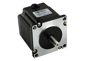
Stepper motors
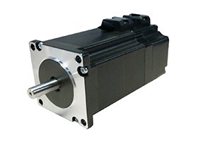
Stepper motors
Stepper motors
Keep your sourcing team on the same page.
We use cookies to keep this site working and measure website usage. Cookie & privacy details
 LinkedIn
 Facebook
 X
 WhatsApp
 Email