

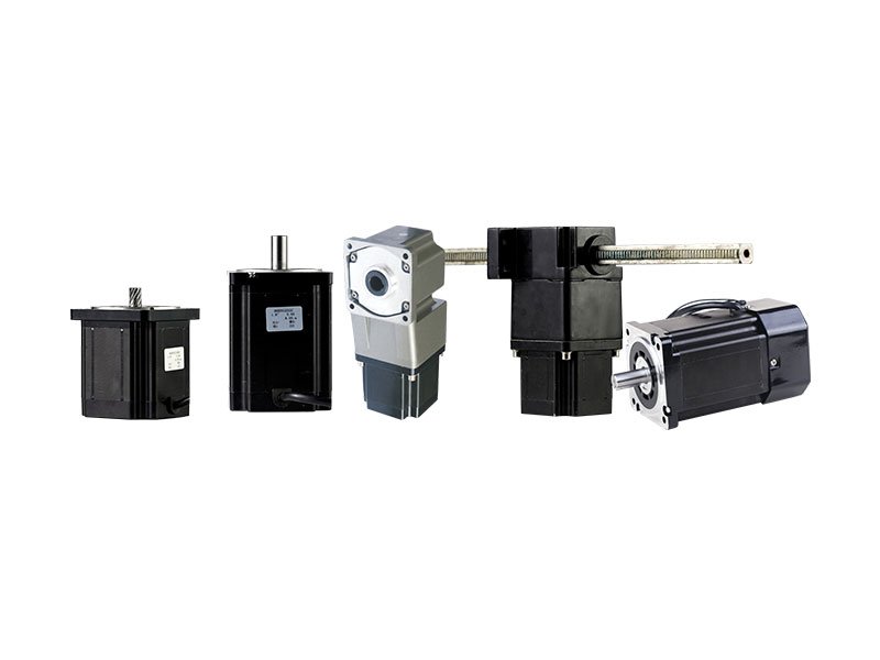
Stepper motors
86BYG hybrid stepper motor series
SANMEN TAILI MOTOR CO., LTD.- Phases
- Two-phase / three-phase options
- Insulation
- Class B
 0
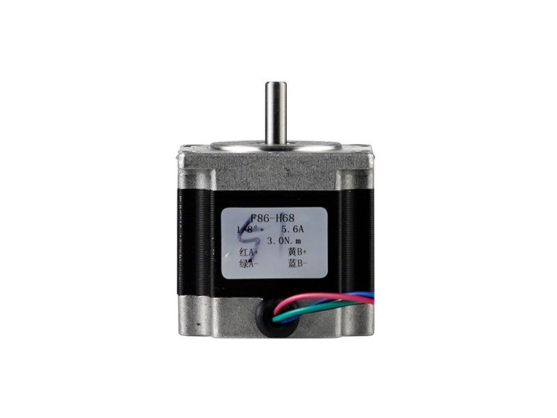
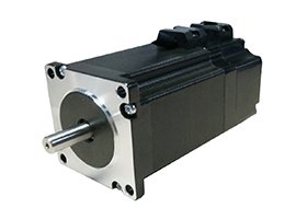
Manufacturer catalogue image · Series illustration

Catalogue series · Exact configuration and availability confirmed by the manufacturer.
The 57BYG frame designation is not a complete replacement specification. TAILI’s six 57BYG250-H entries span 0.45–2 N·m holding torque and 2–4 A rated current, while its connection illustrations include both two-phase and three-phase arrangements. Start with the complete suffix and the delivered lead arrangement before matching an existing driver or mounting plate.
Each row lists a 1.8° step angle. The voltage column is explicitly driver operating voltage, not a voltage to apply directly to a stationary winding. Holding torque is a stationary rating; it does not describe available torque at operating speed.
| 57BYG250 suffix | Holding torque | Rated current | Driver supply | Phase inductance / resistance |
|---|---|---|---|---|
| 41H | 0.45 N·m | 2 A | 24 V | 3.5 mH / 1.5 Ω |
| 52H | 0.8 N·m | 2.5 A | 24 V | 3.4 mH / 1.3 Ω |
| 56H | 1 N·m | 2.5 A | 24 V | 2.5 mH / 1.2 Ω |
| 76H | 1.2 N·m | 3 A | 24 V | 2 mH / 0.48 Ω |
| 82H | 1.5 N·m | 3 A | 24 V | 2 mH / 0.8 Ω |
| 115H | 2 N·m | 4 A | 40–60 V | 3.5 mH / 1 Ω |
The two-phase four-lead diagram identifies red A+, green A−, yellow B+ and blue B−. A replacement still needs the selected winding’s current limit and a compatible driver; identical wire colours do not establish that an old current setting is correct.
The two-phase six-lead illustration adds white Ac and black Bc centre taps to those four phase-end colours. Specify whether the application uses full windings or centre taps and obtain the matching current setting. Do not join the extra wires merely to make the new harness resemble a four-lead motor.
The three-phase diagram marks red U, green V and yellow W, but the accompanying table instead lists black U, white V and red W. These two colour assignments conflict. State the required three-phase configuration in the enquiry and obtain the delivered motor’s terminal identification; neither assignment should be silently selected as the universal wiring instruction.
The bare-motor drawing shows a 57 mm face, four 5 mm mounting holes on a 47.1 mm square pattern, a 38.1 mm locating register and an 8 mm shaft projecting 20.5 mm. The shaft has a flat dimensioned at 7.5 mm across the reduced section. Check the register, coupling fit and shaft projection together; body length alone is not enough to establish a drop-in replacement.
A separate assembly drawing shows a 61 mm gearbox face, a 49.5 mm mounting pattern and a 30 mm output-shaft projection. Additional drawings show horizontal and vertical rack arrangements. These are not alternative dimensions of the bare 57 mm motor. A geared or rack-drive order needs the complete assembly drawing, selected transmission ratio and load requirement.
The displayed torque curves use 57BYG250A/B/C/D labels, whereas the winding table uses 41H through 115H suffixes. No mapping between those naming systems is provided. For a running-torque decision, request the curve identified with the exact H-suffix motor, supply voltage, configured current and driver. Do not attach the strongest displayed curve to the 115H simply because it has the highest holding torque.
TAILI lists −20°C to +50°C ambient, class B insulation and a maximum motor surface temperature of 80°C at rated current. The 80°C figure is a surface-temperature limit, not an 80 K allowable temperature rise. For an enclosed installation, specify ambient temperature, standstill duration and duty cycle, then verify the motor surface temperature with the actual current setting and mounting arrangement.
CATALOGUE OVERVIEW
TAILI lists the 57BYG as a hybrid stepper family with two-phase and three-phase options. The manufacturer specifies class B insulation, a −20°C to +50°C ambient operating range and step accuracy of 5%. Detailed winding and dimensional drawings accompany the series.
Choose the phase configuration and current rating together with the stepper driver. For integration, check shaft dimensions, the locating pilot and alignment with the driven load. Request the exact model torque-speed curve rather than treating the frame designation as a torque rating.
Model / series reference: 57BYG
Specifications describe a series range; confirm which ratings apply together to the quoted model.
Confirm mounting and shaft dimensions against the drawing for the quoted configuration.
Stepper motors
Stepper motors
Stepper motors
Stepper motors
Keep your sourcing team on the same page.
We use cookies to keep this site working and measure website usage. Cookie & privacy details
 LinkedIn
 Facebook
 X
 WhatsApp
 Email