

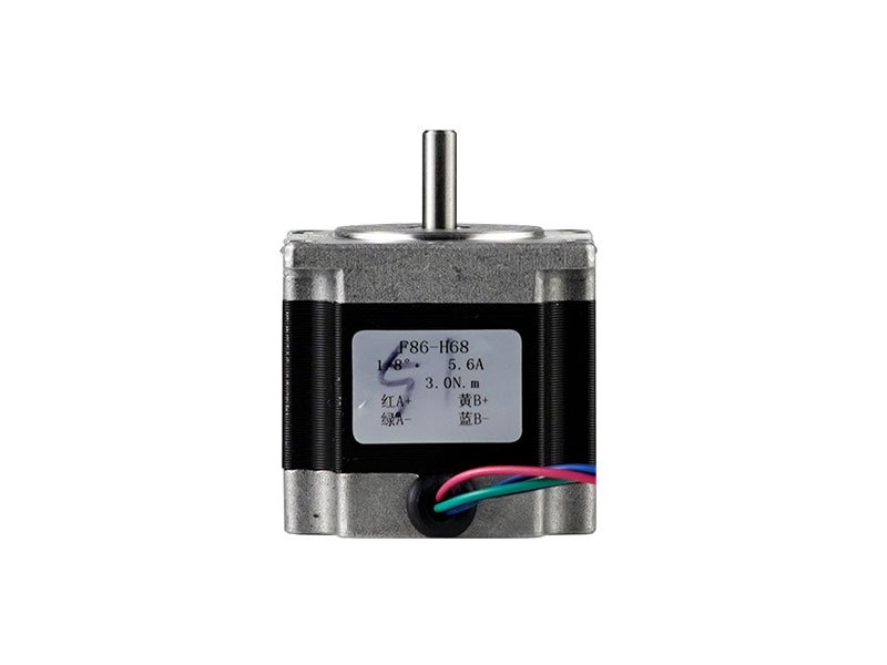
Stepper motors
57BYG hybrid stepper motor series
SANMEN TAILI MOTOR CO., LTD.- Phases
- Two-phase / three-phase options
- Insulation
- Class B
 0
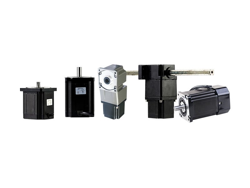
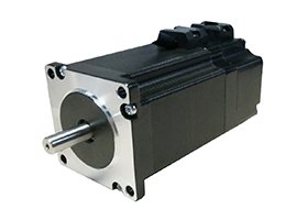
Manufacturer catalogue image · Series illustration

Catalogue series · Exact configuration and availability confirmed by the manufacturer.
TAILI lists five 86BYG250-H motors and five 86BYG250Z-H alternatives with matching electrical ratings. Each Z entry is 38 mm longer and 0.55 kg heavier than its corresponding non-Z entry. That distinction matters in a replacement: the same holding torque does not mean the same rear clearance or assembly mass.
The paired values below come from the same catalogue table. All ten entries list a 1.8° step angle and 60 V driver operating voltage. The table does not define the Z suffix, so it is not evidence of a particular brake, encoder or feedback option.
| Holding torque / current | 86BYG250 model | Length / mass | 86BYG250Z model | Length / mass |
|---|---|---|---|---|
| 2.4 N·m / 4.3 A | 78H | 78 mm / 2.2 kg | 116H | 116 mm / 2.75 kg |
| 4 N·m / 4.5 A | 99H | 99 mm / 2.9 kg | 137H | 137 mm / 3.45 kg |
| 6 N·m / 5 A | 115H | 115 mm / 3.7 kg | 153H | 153 mm / 4.25 kg |
| 8 N·m / 5.8 A | 145H | 145 mm / 4.8 kg | 183H | 183 mm / 5.35 kg |
| 12 N·m / 7.5 A | 155H | 155 mm / 5.3 kg | 193H | 193 mm / 5.85 kg |
The 115H/153H pair is listed at 5 A, 7.1 mH and 0.8 Ω per phase; the 155H/193H pair is listed at 7.5 A, 7.8 mH and 1 Ω. Replacing a 6 N·m motor with a 12 N·m entry therefore requires a current-capability and thermal check. The 60 V catalogue value describes the driver supply, not a direct winding connection.
The page shows 86BYG250 curves at 50 V, 86BYG350 curves at 60 V and 86BYGH350 curves at 220 V. The plotted 250 motors use A–E labels rather than the H-length suffixes in the parameter table. The 220 V graph cannot validate a 60 V 86BYG250-H order, and a suffix-to-curve mapping is needed before using a plotted torque at speed to select one of the ten entries above.
The displayed graphs use 0.12° per command step and show 100,000 pulses/s corresponding to 2,000 rpm. That conversion is specific to 3,000 command steps per revolution: rpm equals pulses/s × 60 / steps per revolution. If the actual driver subdivision differs, the same pulse rate means a different shaft speed. Ask for the required load torque at the actual rpm, acceleration and configured current rather than ordering from holding torque alone.
The page’s installation section currently displays a bare-motor drawing dimensioned with a 57 mm face and a second drawing labelled as a 57 motor with a size-60 gearbox. Those drawings do not establish the 86BYG flange, pilot or output shaft. Request an approved drawing carrying the exact 86BYG250 or 86BYG250Z suffix, including the rear clearance, before drilling the mounting plate or purchasing a coupling.
The electrical illustrations include two-phase four-lead, two-phase six-lead and three-phase three-lead connections. They are alternatives, not one common harness. Provide the existing driver model and a labelled connector drawing with the enquiry, and have the motor’s phase arrangement and current setting confirmed against the delivered configuration.
If the application needs a holding brake or encoder, name that requirement separately from the Z suffix and obtain its voltage, terminals, function and complete assembly drawing. The paired length and mass figures alone cannot prove those functions, and a stationary holding-torque rating does not establish load retention after power loss.
CATALOGUE OVERVIEW
TAILI lists the 86BYG as a hybrid stepper family with two-phase and three-phase options. The manufacturer specifies class B insulation, a −20°C to +50°C ambient operating range and step accuracy of 5%. Detailed winding and dimensional drawings accompany the series.
Choose the phase configuration and current rating together with the stepper driver. For integration, check shaft dimensions, the locating pilot and alignment with the driven load. Request the exact model torque-speed curve rather than treating the frame designation as a torque rating.
Model / series reference: 86BYG
Specifications describe a series range; confirm which ratings apply together to the quoted model.
Confirm mounting and shaft dimensions against the drawing for the quoted configuration.
Stepper motors
Stepper motors
Stepper motors
Stepper motors
Keep your sourcing team on the same page.
We use cookies to keep this site working and measure website usage. Cookie & privacy details
 LinkedIn
 Facebook
 X
 WhatsApp
 Email